Thursday, April 17, 2014

Its April, Fools.

It has been super busy around here and I haven't had a chance to post in a while. I have good news and bad news alike.

The Bad

The bad news is probably the thing that hurts the most. After much waiting I found out a few weeks ago that I did not make it into the third round of the Arch Grants. But in that, there is a silver lining. I learned a ton on starting a business, making a pitch and doing all of the things start ups need to do. Once I receive my feedback from the Arch Grants committee I will re approach the work I did and try again next year.

Also my mighty little Ultimaker has been sick for a little while. There were alot of failed and terrible prints coming out of it. It even started to smoke after the temperature sensor became disabled and the PEEK melted due to excess heat! After alot of work trying different things I managed to get it running like a champ again. Turns out the main issue was a chipped nozzle. After doing all of my repairs it has been running nearly non-stop for the last week making parks for El Monstro as well as several other projects.

The Good

While both bits of bad news had upsides, this is all good news.

I am going to be doing a test assembly of El Monstro next week! I have all of the parts for the frame done and I have a little bit of work to do with some aluminum plates and it will be ready to go! From there I will be making adjustments and seeing where any issues may be. The goal is to have the frame assembled by April 25th. From there it will be getting the Z axis constructed and all the steps that follow. But I won't bore you with that dear readers.

Aside from that, we have also acquired a few more scanners so that we can do even more 3D scanning!

Finally, once I am reworking the design for the filament extruder. There are some modifications that need to be made based on what I have learned with the first go round and from talking to the folks at Xtrution. Namely adding in a cooling fan to the pipe behind the band heater and adding in a water cooling system with an auto winder. Its alot of changes and upgrades but it should all be worth it in the end considering the savings on filament it will create.

Updates on the assembly of the big machine will follow in a week or so. Please stay tuned!

Wednesday, March 19, 2014

Arch Grant, Round Two!

I was accepted to the second round of the Arch Grant entrepreneur and startup grant on March 10th and the submission for the second round was on the 17th. I submitted my pitch video and here it is!


I will be continuing to update the blog as the design progresses. I am currently playing with a few different designs for the Z axis, which is why I haven't posted anything recently.


More posts on the big machine to come! Keep watching!

Monday, March 3, 2014

Gantry Design DONE!

After several revisions and different models the Gantry parts are done being designed.

Naturally they will change slightly and go through revisions as the parts go from digital to reality but for now they can all be printed and tested! One revision that will be done before moving onto the next piece in my design list is changing out the Dual V Wheels with Solid V Wheels. The Solid V Wheels can handle the loads of the gantry better than the Dual V's so they will be an easy replacement. The Solid V's are a slightly smaller diameter (very very slight) but its enough that I want to make sure that I don't have to change the placement of the mounting holes.

Here is are a few pics of the gantry so far.


And here are the individual parts. The first of them is the Extruder_Plate. Just like the name says, the extruder will be mounted to this plate.


The next part is the Ganty_Mount bracket. I went through 5 revisions of this part before finally ending up with this design. Each revision was a ground up take on the design which took a while each time. On the back side of the bracket there are little "wings" or "horns". Those are going to be the points that the belts mount to allowing the gantry to move.


Next up on the design list is the Z axis scissor lift. This one will be an interesting challenge. In some of my pre-drafting spitball designs I came up with about 16 different parts that I will need to model for it. Many of those are used multiple times which means that the total part count is closer to around 50 parts in the the Z axis assembly. That count doesn't even include the wheels or screws! Looks like I have quite a bit to be working on, so best get to it!

Comments? Questions? Answers?

Just post in the comments section below!

Saturday, March 1, 2014

Still Working On Things

The most up to date version of the El Monstro's design is coming along. I am having some issues getting the gantry redesigned to support two pieces of extruded aluminum to help with the deflection of the full 1500mm distance. I have some designs that I am working on currently but they are still in the early stages of design.

Here are a few pics of the frame so far using the new corner blocks. In all there are 3 different corner blocks used in the frame. The Base, which covers the 4 bottom corners and vertical rails. The Motor Mount corner  blocks, which are at the top of the machine holding the motors in place. Finally the Idler Mount's which allow the idler pulleys to be mounted so that the belts can loop back to the driving stepper motors.


A close up view of one of the corner blocks shows a high lighted hole at the bottom of the corner block. This corner bottom hole is used to attach tension cables to in order to allow a stronger structure without the need for an external super structure.


More updates to follow as I make progress on the design!

Saturday, February 22, 2014

It has been quite a while since I have posted on here. That is mainly due to there being very few things to report and update.

I mentioned in the post from September that I would have a few updates regarding the status and future of El Monstro. Well I can talk a bit more about that here in a single post.

Present

The physical build has stalled for the time being. This is due in part to lack of funding but also due to other projects coming up and work in general.

I have continued to refine the design digitally. I have been printing some test parts but with my current 3D printer on the fritz I have to do some repair work before I can print any more test parts.

I am currently on version 3 of the El Monstro design. I have also been working on redesigning the hot end and doing some general work to bring the over all mechanical design into better shape.

The Future

I have recently applied for an Arch Grant! This would be a HUGE step in moving forward. While I am not looking to produce the printer's themselves, it would still help in the development of the large scale printer so that giant prints could be made.

An Arch Grant would be the next big step in allowing me to go full time as a maker. But that is just the first step. The steps that follow will be the important ones that would help me to sink or swim.

I have partnered with a friend and fellow 3D printing guru, Ryan Hendrickson. Together I feel that we will be able to TAKE OVER THE WORLD... of large scale 3D printing though FDM/FFF printers.

I am working on a model to post on here as a sign on where things are headed for us in the design and build of El Monstro v3. I have been working on ways to incorporate dual extrusion, a stronger build platform, a heated bed and a direct feed filament maker.

Ryan has been looking into things on the software side in order to help keep things moving from all angles. He has been researching and working on code to allow the big machine to work fast and effectively. Code isn't my strong suite but Ryan is great at it and I know that he will come up with something great.

The last exciting thing to mention is that with the help of one of the members of Arch Reactor (hacker space) we will be starting on building a filament grinder soon as well! This is a big deal as it helps to lower filament costs from failed prints!

We will also be starting work on a website soon so look for updates with links!

Keep checking back! More to come!

Saturday, September 28, 2013

New Posts In The Works

Im On It!

Folks thank you for all of the support that was shown to me at the World Maker Faire. Also thank you to my sponsors OpenBuilds Part Store and Ultimaker for all of the help that you provided me in this project. Also a Huge thank you to Arch Reactor Hacker Space in St. Louis MO. I am a member there but I am and always will be very grateful for all of the support I have received from them over this project.

Also, check out DVice.com's article on the Hidden Gems of Maker Faire 2013! The fourth image at the bottom of the article shows me and El Monstro! I was even called insane! On the internet of all places! How awesome is that! Someone finally recognized my insanity. Validation is rather nice.

Hidden gems at Maker Faire NY 2013


I wanted to let everyone out there know that I have 3, yes 3 posts in the works. I need to snap a few more images of everything and keep knocking through the rather long posts detailing the build.

Big Update: Part 1, "The Monster Lives"

This update will bring folks up to date from where I left off up to and through the World Maker Faire.

Big Update: Part 2, "The Filament Machine!"

This post will chronical the build of the filament machine from start to current status. There were a TON of questions about the filament machine at Maker Faire and I hope to post answers to those questions as well as show alot more about how the machine was built. 

Big Update: Part 3, "The Future of El Monstro"

The last of the three part updates will talk about what I learned from others at Maker Faire as well as where I see things going for both me and El Monstro. There are alot of changes in the works and I will talk about them all!

Keep checking back! There is a TON of information about the build and all of the projects involved with the build about to come out! Stay tuned!

Sunday, August 4, 2013

Sponsorship's, Nozzles and Extruded Aluminum! Oh My!

Sponsorship's, Nozzles and Extruded Aluminum! Oh My!

Oh My!

This is a little in reverse order but its worth it! Tonight I received my confirmation letter for Maker Faire! WoooooooooooooooooooooOOOooOoOoooo!!! Thank you very much to the folks at Make for allowing me to be a part of the Maker Faire!!!

Sponsorship!

I would like to give a big, BIG thank you to Ultimaker who has graciously offered to help sponsor the El Monstro build! They offer will definitely help to move things forward in a very positive way. I have been using an Ultimaker 3D printer for about seven months now and I love it. Without it this whole project would not be possible. If you have some time please stop by their website and check out their amazing machine!


In my last post I talked about making another board for the thermocouple to communicate with the RUMBA board. With the help of Ultimaker I am looking at switching electronics to the Ultimaker Board. I would swap out the Stepper Drivers for the Pololu black stepper drivers that I had intended to use with the RUMBA board. The reason being that the Pololu black stepper drivers can handle a higher amperage which means that I can drive more power to my stepper motors (all 6 of them that I am looking at using). This also means that I can use the Ultimaker thermocouple board to help simplify everything.

Nozzles!

The next bit of news is just as exciting as the last! Mostly because I am learning to use the mini metal lathe. This is a tool that I have wanted to learn to use for a long time and now I finally have a reason to. Its a rather addicting machine to learn to use. Just like a laser cutter, CNC machine or 3D printer, you sometimes find yourself saying, "I could machine that..."

With this I decided to design my own nozzle that is a PrusaNozzle variant. First thing I did was look over the designs of the PrusaNozzle from Joseph Prusa's website. You can find the PDF version of the plans through this link.


From here I wanted to work on the lathe a bit before I created a design so that I understood how it worked better and also so that I could get an idea of what tools I had readily available at the hacker space. My first attempt wasn't the greatest thing ever but keep in mind that it was the second time I have ever used a metal lathe. It didn't turn out all that well because the hacker space did not have the right tools for creating the cooling fins along the shaft.

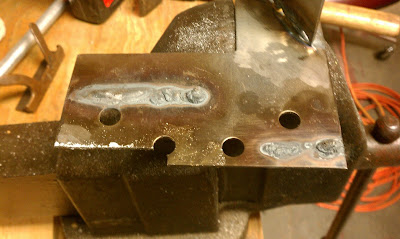
So after talking to another member he offered to let me use some of his scrap tool steel (tools steel is a hardened steel that holds an edge very well and is well suited for making tools from) plate that he had been practicing his TIG welding on.


It was an ugly piece of scrap but it was free tool steel none the less! So from here I needed to make a tool that would both fit in the lath and create the correct sized space between the fins. The bottom left corner that is missing is where I sawed a piece of plate off. I then tool the piece to the bench grinder to shape it and then filed it down further to hone the tip and thickness. This is what I ended up with.


I had to cut the notch into the piece in the center to lower the position that the tool sat in the tool holder so that the tip of the bit would hit the material correctly. After a few test cuts and adjustments I was able to get it to cut to the correct depth and thickness (1.5mm). 

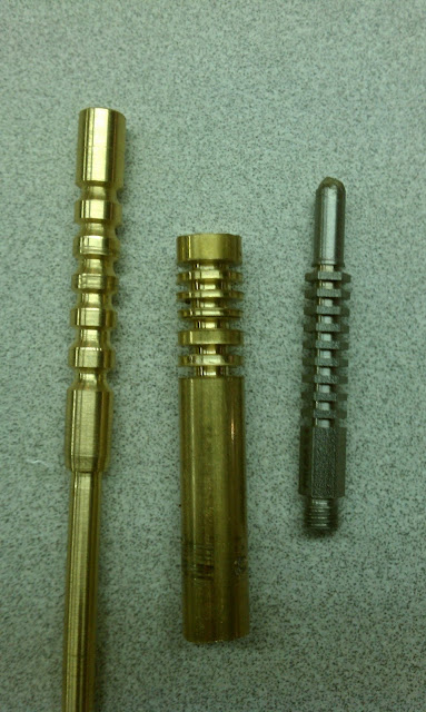
Here is an example of my progress.

Left - First Attempt; Center - Second Attempt/Test; Right - PrusaNozzle


So now that I had a bit that works well and more experience with the the metal lathe I came up with a design. It is a longer version of the PrusaNozzle with a larger diameter hole at the tip.


It was only after I began making the nozzle did I realize that I designed the nozzle a bit to long. It was a simple fix to just skip several of the fins and go right to the back portion. The back portion of the nozzle was left at a larger diameter to allow me some room to create threads. In addition I left it larger because at the time I wasn't sure how I was going to mount the nozzle to the printer. I have since figured out how to mount it and I will have that in a later update.

So now that I have a plan I cut off a hunk of 3/8" round 360 brass and went to work! I machined down the bulk of the nozzle to the outer diameter of the fins. Then I marked out the start and end of the fins (the small notch at the front and back), took more material off the tip to get it down to the correct size and finally I added the angle to the front of the nozzle to give it a more pointed shape. I also used a tiny drill bit (0.8 mm) and bored out the tip a little extra deep to make it easier to find when I did the larger bore from the back.


Next I added in the fins. You can see here how it all turned out. I still had to finish the back portion of things though.


So I flipped it around and cut the back portion down to the right diameter then I bored out the back end to 3mm to accept filament. I also threaded the tip so that a heated block could be easily screwed onto it. And here is the result next to a PrusaNozzle!


So the final step was to attach the heater block and see how it all looks.


Success! I will be testing it out this coming week to see how it work and if it extrudes filament at the correct diameter (0.8mm).

I am doing everything in 360 brass for the time being until I have more experience and I have made a few more things on the lathe. The goal is to create a version of my PrusaNozzle variant in stainless steel. I picked up a piece of 303 Stainless Steel today from a local metal supplier and I also got a chunk of 1" x 1" 2024 Aluminum.

The idea with the aluminum is that I can create a larger heater block with it. The reason for this because of the higher volume of material that I will be moving through the nozzle.

While at the metal suppliers today I also picked up a few things that may turn out to be an interesting find. They are stainless steel pneumatic quick connects that were buried in a bin in the catacombs of the metal suppliers basement (its a 3 acre in door and outdoor place with a crazy amount of stuff). I need to hit up the hardware store and try to find something that will let me connect the nozzle and the quick connect together.


So the next step is to make another version of my PrusaNozzle variant in brass with a 1mm diameter hole then take a crack at making on in stainless. I will have more updates on my attempt at stainless later in the week.

Extruded Aluminum!

And as the last part of this post, I have received an update from OpenBuilds about the parts that I ordered a while ago for the frame. They will be shipping out soon! So hopefully I will have them soon so that I can get more things going!

I will have more updates in a few days! Stay tuned!