Saturday, September 28, 2013

New Posts In The Works

Im On It!

Folks thank you for all of the support that was shown to me at the World Maker Faire. Also thank you to my sponsors OpenBuilds Part Store and Ultimaker for all of the help that you provided me in this project. Also a Huge thank you to Arch Reactor Hacker Space in St. Louis MO. I am a member there but I am and always will be very grateful for all of the support I have received from them over this project.

Also, check out DVice.com's article on the Hidden Gems of Maker Faire 2013! The fourth image at the bottom of the article shows me and El Monstro! I was even called insane! On the internet of all places! How awesome is that! Someone finally recognized my insanity. Validation is rather nice.

Hidden gems at Maker Faire NY 2013


I wanted to let everyone out there know that I have 3, yes 3 posts in the works. I need to snap a few more images of everything and keep knocking through the rather long posts detailing the build.

Big Update: Part 1, "The Monster Lives"

This update will bring folks up to date from where I left off up to and through the World Maker Faire.

Big Update: Part 2, "The Filament Machine!"

This post will chronical the build of the filament machine from start to current status. There were a TON of questions about the filament machine at Maker Faire and I hope to post answers to those questions as well as show alot more about how the machine was built. 

Big Update: Part 3, "The Future of El Monstro"

The last of the three part updates will talk about what I learned from others at Maker Faire as well as where I see things going for both me and El Monstro. There are alot of changes in the works and I will talk about them all!

Keep checking back! There is a TON of information about the build and all of the projects involved with the build about to come out! Stay tuned!

Sunday, August 4, 2013

Sponsorship's, Nozzles and Extruded Aluminum! Oh My!

Sponsorship's, Nozzles and Extruded Aluminum! Oh My!

Oh My!

This is a little in reverse order but its worth it! Tonight I received my confirmation letter for Maker Faire! WoooooooooooooooooooooOOOooOoOoooo!!! Thank you very much to the folks at Make for allowing me to be a part of the Maker Faire!!!

Sponsorship!

I would like to give a big, BIG thank you to Ultimaker who has graciously offered to help sponsor the El Monstro build! They offer will definitely help to move things forward in a very positive way. I have been using an Ultimaker 3D printer for about seven months now and I love it. Without it this whole project would not be possible. If you have some time please stop by their website and check out their amazing machine!


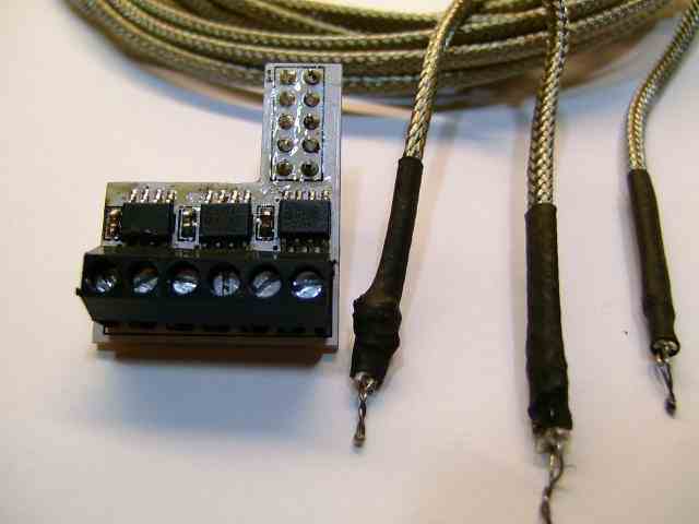
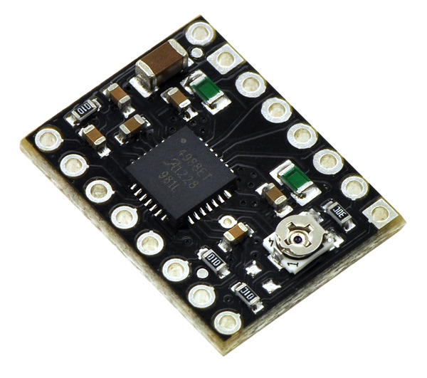
In my last post I talked about making another board for the thermocouple to communicate with the RUMBA board. With the help of Ultimaker I am looking at switching electronics to the Ultimaker Board. I would swap out the Stepper Drivers for the Pololu black stepper drivers that I had intended to use with the RUMBA board. The reason being that the Pololu black stepper drivers can handle a higher amperage which means that I can drive more power to my stepper motors (all 6 of them that I am looking at using). This also means that I can use the Ultimaker thermocouple board to help simplify everything.

Nozzles!

The next bit of news is just as exciting as the last! Mostly because I am learning to use the mini metal lathe. This is a tool that I have wanted to learn to use for a long time and now I finally have a reason to. Its a rather addicting machine to learn to use. Just like a laser cutter, CNC machine or 3D printer, you sometimes find yourself saying, "I could machine that..."

With this I decided to design my own nozzle that is a PrusaNozzle variant. First thing I did was look over the designs of the PrusaNozzle from Joseph Prusa's website. You can find the PDF version of the plans through this link.


From here I wanted to work on the lathe a bit before I created a design so that I understood how it worked better and also so that I could get an idea of what tools I had readily available at the hacker space. My first attempt wasn't the greatest thing ever but keep in mind that it was the second time I have ever used a metal lathe. It didn't turn out all that well because the hacker space did not have the right tools for creating the cooling fins along the shaft.

So after talking to another member he offered to let me use some of his scrap tool steel (tools steel is a hardened steel that holds an edge very well and is well suited for making tools from) plate that he had been practicing his TIG welding on.


It was an ugly piece of scrap but it was free tool steel none the less! So from here I needed to make a tool that would both fit in the lath and create the correct sized space between the fins. The bottom left corner that is missing is where I sawed a piece of plate off. I then tool the piece to the bench grinder to shape it and then filed it down further to hone the tip and thickness. This is what I ended up with.


I had to cut the notch into the piece in the center to lower the position that the tool sat in the tool holder so that the tip of the bit would hit the material correctly. After a few test cuts and adjustments I was able to get it to cut to the correct depth and thickness (1.5mm). 

Here is an example of my progress.

Left - First Attempt; Center - Second Attempt/Test; Right - PrusaNozzle


So now that I had a bit that works well and more experience with the the metal lathe I came up with a design. It is a longer version of the PrusaNozzle with a larger diameter hole at the tip.


It was only after I began making the nozzle did I realize that I designed the nozzle a bit to long. It was a simple fix to just skip several of the fins and go right to the back portion. The back portion of the nozzle was left at a larger diameter to allow me some room to create threads. In addition I left it larger because at the time I wasn't sure how I was going to mount the nozzle to the printer. I have since figured out how to mount it and I will have that in a later update.

So now that I have a plan I cut off a hunk of 3/8" round 360 brass and went to work! I machined down the bulk of the nozzle to the outer diameter of the fins. Then I marked out the start and end of the fins (the small notch at the front and back), took more material off the tip to get it down to the correct size and finally I added the angle to the front of the nozzle to give it a more pointed shape. I also used a tiny drill bit (0.8 mm) and bored out the tip a little extra deep to make it easier to find when I did the larger bore from the back.


Next I added in the fins. You can see here how it all turned out. I still had to finish the back portion of things though.


So I flipped it around and cut the back portion down to the right diameter then I bored out the back end to 3mm to accept filament. I also threaded the tip so that a heated block could be easily screwed onto it. And here is the result next to a PrusaNozzle!


So the final step was to attach the heater block and see how it all looks.


Success! I will be testing it out this coming week to see how it work and if it extrudes filament at the correct diameter (0.8mm).

I am doing everything in 360 brass for the time being until I have more experience and I have made a few more things on the lathe. The goal is to create a version of my PrusaNozzle variant in stainless steel. I picked up a piece of 303 Stainless Steel today from a local metal supplier and I also got a chunk of 1" x 1" 2024 Aluminum.

The idea with the aluminum is that I can create a larger heater block with it. The reason for this because of the higher volume of material that I will be moving through the nozzle.

While at the metal suppliers today I also picked up a few things that may turn out to be an interesting find. They are stainless steel pneumatic quick connects that were buried in a bin in the catacombs of the metal suppliers basement (its a 3 acre in door and outdoor place with a crazy amount of stuff). I need to hit up the hardware store and try to find something that will let me connect the nozzle and the quick connect together.


So the next step is to make another version of my PrusaNozzle variant in brass with a 1mm diameter hole then take a crack at making on in stainless. I will have more updates on my attempt at stainless later in the week.

Extruded Aluminum!

And as the last part of this post, I have received an update from OpenBuilds about the parts that I ordered a while ago for the frame. They will be shipping out soon! So hopefully I will have them soon so that I can get more things going!

I will have more updates in a few days! Stay tuned!

Monday, July 22, 2013

Moving Forward

Moving Forward

I received word that due to some issues with the manufacturer my shipment of parts from OpenBuilds is going to be delayed another week. Things happen, it sucks, but you have to continue forward if you want to take something from the drawing board to reality. With a project like El Monstro there are many other parts that I can actually continue forward with. Some hinge on testing them with the assembled frame, others... not so much.

So in the spirit of, "Adapt and overcome" I have shifted focus for the time being to getting the thermocouple to communicate with the RUMBA board and working on the extruder nozzle and heater block.

First the thermocouple. The RUMBA board is set up to use a thermistor, not a thermistor. What is the difference between the two? Why that's... kinda simple? The Thermistor and Thermocouple work in different ways. Both measure temperature but in different levels of accuracy and both have a range of temperatures that vary widely between the two.

Here are the cliff note versions for our purposes in 3D printing. If you want to know more details about Thermistors and Thermocouples then check out the links.

Thermistors create an analogue signal by measuring resistance through heat. They also have a smaller temperature range of around -50 C to 300C depending on the model of thermistor. They are generally more accurate but due to their narrow range in temperature they are usually used in lower temperature applications that require more accuracy. For more information, click here

Themocouples create voltage when heat is applied to them. That voltage is then measured to determine the temperature being monitored. Thermocouples are slightly less accurate as they have a harder time distinguishing between temperature fluctuations of 1 degree C. However, they do have a much wider temperature range. Thermocouples can measure temperatures in the range of -50 C to 1300 C (about 2600 F) for consumer grade models. The higher end versions can get as high as 1800C (about 3600 F!!!).

The reason that I am going to be using a thermocouple instead of a thermistor is because a printer with a build volume this large may be able to work with materials that require a temperature of more than 300C. A good example is Polycarbonate which requires temperatures of about 265C or higher depending on the machine. That means that if I were to run Polycarbonate through the printer then I would be coming close to the maximum temperature range of the thermistor, which could cause issues.

So, how do you make a RUMBA board that requires a thermistor use a thermocouple instead? Simple, use another board.

After alot of digging and question asking I finally stumbled upon the following.


The picture above is from a RepRap forums post that talks about using thermistors for higher temperatures. The person who posted the picture stated that RepRapDiscount.com is working on supplying these shields for the expansion slots of RUMBA boards to allow people to use thermocouples. After some more digging I found a post on the RUMBA forums asking the same thing I was wondering, "When will those adon boards be available?!" The answer has yet to come.

So with no answer on that front I dug a little more and found another post on the same RUMBA forums that gave users a chance to download the schematics and board layouts for the adon board! The only issue with the files is that they were created with the program Altium Designer. I used my burner gmail account to register and download the Altium Designer Viewer from a third party website so that I could atleast see the files. After sending them off to a few friends of mine for some much needed help they came through in flying colors with an Eagle file that I could use to send off to a board house or edit a bit more and turn into a single layer board.

Here is the 2 layer version of the board that I can send off to have made.


The other option is making the board using some other options with help from a few more members of the Arch Reactor Hackerspace here in St. Louis. I am not sure which way I am leaning towards but either way I will have to stuff (solder all the parts onto) the board. I will have more updates on all of this by next week.

A huge, HUGE thank you to Bruce and Travis for all of your help in getting this figured out!

The Extruder

The other thing that I have been working on is aquiring metals and parts to make the extruder. I have a few sticks of brass already and a 1 foot stick of 2024 aluminum on its way. I also got in all of the small metric drill bits so that I can make myself a few different sized nozzles to test once everything is up and running.

Since I haven't really ever used a metal lathe before to make... well anything, I am going to have some coaching and I also have some soft (6061) aluminum to play with before I use any of the other pieces that I have. Not much in the way of pictures to show here but I will have some in my next post!

Other Stuff

As a side note I am also working with a few other people on getting a Lyman Filament Extruder made so that I can make my own filament and possibly even let if feed directly into the big printer from the filament extruder. There is also a filament grinder in the works to help break down small and large prints alike into small enough pieces to put into the Lyman Extruder.

Tons of stuff in the works! August is going to be one hell of a busy month.

Wednesday, July 17, 2013

Sponsorship!

A Monster Reborn

I would like to start off this post by giving a big thank you to OpenBuilds for their generosity in sponsoring the giant 3D printer, El Monstro! Part of the reason for the delay in posts has been from talking to the great folks at OpenBuilds and working on a new model for the printer.

The build is now going to be using the OpenBuilds V-Slot Extruded Aluminum pieces as a large part of the machine. The advantage with the V-Slot is the ability to quickly and easily assemble the parts, use standard v groove bearings and choose from their great number of plates!

 
I am finishing up the model using the OpenBuilds parts and I will have it up in a few days.

I have also been working on designs and ideas for an extruder nozzle. One of the issues that I have had to approach with an extruder for a large scale printer is how to heat enough material for a larger diameter nozzle. One of the solutions that I came up with was using a longer heated chamber with two heating cartridges allowing a larger volume of material to be readily heated. Ultimately though I think that I am going to do some testing with a spare heating block and nozzle that I have before I look into using two heater block. I am going to drill out the head from 0.4mm to 0.8mm and do a few tests. If need be I will step up to a 1mm bore.

So lots of things in the works! Tons to do! The biggest thing that is delaying things right now is waiting for items to arrive so that I can continue working. I feel like a kid waiting for Christmas morning!

Monday, July 8, 2013

Quick Update

Its been a little while since I posted any updates to El Monstro. I wanted to post that I am working on getting a few larger posts up and going but for now the build is at a stand still while I work through some design issues. The larger posts will cover the design issues that I am working through and hopefully show some progress on the build.

The rods that I was planning to use for the gantry turned out to be to thin for what I need. Because of this I had two options.
1) Get bigger rods (and bearings and pulleys)

2) Change to a different style of gantry that runs on tracks instead of using hardened rods.

I chose the latter. So for now I am working on getting things changed over to use a track based system. That means finding the correct parts to use and designing a whole slew of new parts then getting them printed! I am going to try to get a new post up about everything Monday night or Tuesday night. For now I leave you with this. A sample of all of the corner blocks that I ran through a band saw, drilled and counter bored by hand. Makes me wish I had a CNC machine for this kind of stuff!


Monday, June 24, 2013

El Monstro: The Design

El Monstro: The Design

The idea of a large scale 3D printer is on that I have had for several years. I have attempted a few times before to get the project off the ground but it never really went anywhere until recently. I am still working on a Bill of Materials (BOM) and a list of suppliers. That will be in a later update once I have more of the printer up and running.

The Past

The difference in the failed attempts and the one that is succeeding is inspiration and friends. Before when I attempted to design the large scale machine I had little to no experience with 3D printing. It was just something that I thought was "really cool" and that I wanted to be a part of. It wasn't until I attended the Fab Academy in Rhode Island that I had a much greater exposure to 3D printing and digital fabrication/digital design. Being able to work with a 3D printer, a laser cutter and a CNC machine while in the Fab Academy helped me to understand the tools of the trade much better and how to design with them. Once I understood that my designs began to rapidly change and come together when I approached a project.

Having friends like Bruce W. and Ryan H.who are people within the world of 3D printing who are working with large scale design helped out immensely. People who I could bounce idea's off of or trouble shoot a concept before designing something to fit a specific need helped greately.

The Present

Having friends like Bruce W. and Ryan H. were some of the biggest help. Bruce built a large scale Ultimaker and was able to print a few large objects for the NYC Maker Fair last year and has been someone who has been assembling and redeigning 3D printers for several years. Ryan H. is a friend that I met at the local Hack Space, Arch Reator. He had one of the early Makerbot CupCake CNC's and has built (and rebuilt) a few of his own 3D printers. Having these people within the world of 3D printing to talk to and bounce idea's off of or trouble shoot a concept before designing something to fit a specific need helped immensely.

All of that being said, the current version of "El Monstro" is the seventh (v. 0.7) version that has come about in the process of designing just this one machine. I have does quite a bit of research, looked at other designs and 3D printers and I have cherry picked a few things here and there that I feel work very well.  The bulk of the original design came from the Ultimaker style gantry and build plate that rises to meet the head. I worked with this mechaical design concept because it combines several attributes very well in a 3D printer that I have found to be important. 
  • The Gantry
  • The Bowden System
  • Simple, solid frame
  • Easy to modify
  • A build plate that does not move in any direction outside of the machine
From here I had to decide which material to use to build the printer and how large to make it. The original idea was to make the machine have a nominal build space of 3'-0" cubed, and to use a wooden or HDPE panel frame. After talking with Bruce W. about how is wooden frame for his scaled up Ultimaker came out and after doing a few initial rough designs I chose to go with extruded aluminum.

Extruded aluminum is a great product with alot of suppliers out there. I used 8020's eBay page to hunt down the parts that would work for me. 

Why eBay? Simple! 8020, like many industrial part suppliers 8020 puts their cut off parts or miscut parts online for sale to help to move their product even if its not a full stick or for a custom order. I was able to save quite a bit on the extruded aluminum by going this route. I was also able to get a .dwg and solid parts version of their different products from their website by simply registering on their website.

With the .dwg from 8020 in hand I was able to make functional 3D models of the parts I intended to use in SolidWorks.


From here I simply extruded the profile to the length that I needed for each iteration of the design. I also based these parts on what was available through 8020 via eBay. This partly influenced my design choices.


Below is an earlier version of El Monstro. The inner two rails to the left and right of the model were to be used with the OpenRail system from Open Builds. OpenRail is a set of V Groove rails that bolt into the T slot portions of many different brands and sizes of extruded aluminum. The plan was to use these rails to help balance and guide the build platform up and down as the printer ran. I eventually changed the design to get rid of the OpenRail system in favor of another system that would simplify the build slightly and help to lower costs. I will get to next.


Around this time the Cerberus 3D printer hit YouTube. Its a delta rostock printer that uses extruded aluminum rails to move the print head along the X, Y and Z axis. That is where I found what I will be using in my printer. The Dual 623 V Roller. These wheels actually fit in the T slot tracks of the extruded aluminum which make it possible for a set of pillow blocks to ride in the grooves to carry the build plate up and down. I like this design because it uses the frame of the machine itself instead of adding more parts to the design.


With these parts now a part of the plan I was able to simplify my design slightly in order to accommodate the way that the build platform would function. With this part set I had all the mechanical basics covered. Overall mechanical design, filament feed method and Z movement.

Electronics!

The next thing I had to look at was the electronics. I chose to go with the new RUMBA board with the Black Pololu A4988 Steper Drivers. The reason for the board is that with a machine this size I might need to drive larger stepper motors with separate drivers to move the Z axis up and down. The RUMBA board also provides an opportunity to upgrade to multiple extruder heads in the future and with the Black Pololu stepper drivers I can push more power to stepper motors than with some of the standard stepper drivers.


Extruder Head!

Next was which extruder head to use. While I get this machine up and running I intend to use the Prusanozzle. This nozel can get up to very high temperatures and since it is made of all stainless steel it is a much more robust hot end with no PEEK or brass parts to deal with. Eventually I plan to change out the head to something bigger to help to offset the speed of prints while still keeping much of the quality the Bowden/Gantry system allows.

More To Come!

That is all for this post for now. Its alot of the basics of the design. A good general over view (many more details next post), which electronics and which hot end I will be using.

Next post will have many more details on specific parts, the gantry design and some of the challenges with it when moving to the large scale, and many other features. This is a HUGE undertaking so there will be many posts just to catch up to where I am today.

Feel free to post comments, questions and suggestions below! Thanks for reading!


Thursday, June 20, 2013

Minions!

Every mad scientist needs his minions!


I did a side project for the hell of it in order to take a step back from some of the work that I have been doing on El Monstro. Its good to do little fun things like this every now and then. I am working on a HUGE post with alot more information as well as more pictures as I begin to assemble the beast and test some parts.

Here are a few pictures of the design process

I started with an image that I found through a random Google search.

From here I took the picture in to Auto CAD and traced out all of the parts. I also made a mono goggle (monoggle?) in keeping with the different versions of the little guys.


Next I took each outline into SolidWorks and offset the outlines to give me a plate for support surrounding the outlines. From there I did another smaller outline to give me the walls needed to cut cookie dough with. The last thing I did in SolidWorks was to add a tiny 45 degree angle to the edge of the cutter to help cut into the dough a bit better.


The last step is to send them off to the printer! And.... Bingo! We are ready to make some minion cookies!


A Monster Is Growing...

Welcome to the blog!

Here I hope to document the process that I am going  through in designing a very large scale 3D printer as well as some of the random objects and projects that I come up with.

Here is the first picture of the test assembly of my giant 3D printer's frame. The giant 3D printer has been dubbed, "El Monstro". It seemed like an appropriately ominous title for such a beast of a project.

The frame measures 4'-3" x 4'-3" x 5'-9".


For a bit of a height reference here I am standing in the center of the frame. I am 5'11" tall.

I will have more pictures and information in the days ahead as I begin to assemble and test El Monstro. 

I will note that the pictures are a TEST assembly to make sure that the holes tapped in the ends of each piece of extruded aluminum were deep enough. There will be much more in the way of corner blocks and other parts to make the frame more rigid.